Manage Installations
Manage Installations is the UMS function that allows you to manage all service-related devices (such as meters, transmitters, backflow devices, etc.) that are installed within the service area. These devices are installed at and associated with specific Locations within UMS, and are managed separately for each individual Location.
Opening Manage Installations
There are several ways to access the Manage Installations function:
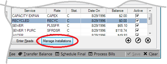
From Account Control Panel > Location:
Open the Account Control Panel for the specific Location in question. Within the Location tab for this Account, click the Manage Installations button under the service details section.
Figure 241: Manage Installations from Account Control Panel
This will open the Manage Installations screen for that Location.
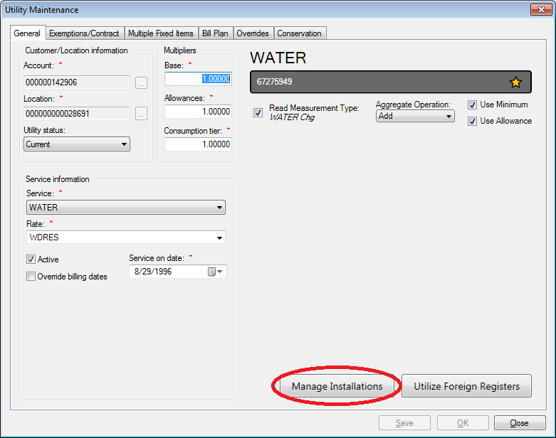
From Utility Maintenance:
Also from within service details section of the Account Control Panel > Location (as described above), select a service and double-click to open the Utility Maintenance window.
Figure 242: Manage Installations from Utility Maintenance
This window will provide device information and allow you to manage installations for only the specific service opened, but you can also open the main Manage Installations function by clicking the Manage Installations button.
Installations Tab
The first tab within Manage Installations is the Installations tab. It contains details for every device (meter, transmitter, remote, backflow) installed at the Location in question. Most of the displayed information is for information only, but some of the fixed details can be changed through the Add and Edit functions.
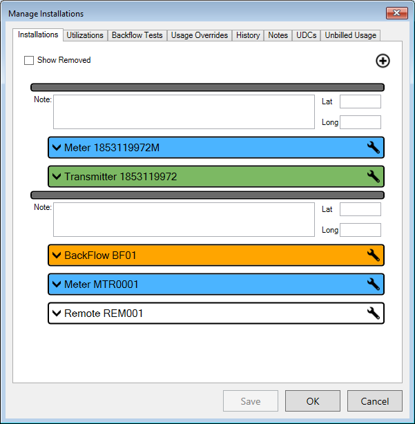
Figure 243: Manage Installations – Installations Tab
All installed devices for the Location are listed. They are organized within this tab in sections called inventory locations, indicated by a gray bar heading each group.
Note: The inventory location groups should not be confused with the UMS Location for the Account. Any UMS Location may have any number of device locations, as required to clarify where the items are within the Location.
Inventory Location Groups
The devices under each gray location header are associated together in a specific place within a Location. The inventory location groups may also be used to clarify which items are associated together.
Each device location grouping will have a header that includes a Note box and two fields called Lat and Long.
Lat and Long are optional items meant for geographic information (latitude and longitude), used to indicate the physical position of the inventory device(s) within the Location property.
Note is a field designed for references or notes concerning the location. This note follows the inventory location, regardless of whether some or all devices are removed or changed out.
At the top of the Installations list is the Add button.
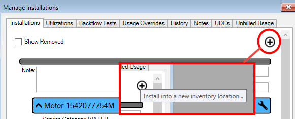
Figure 244: Manage Installations - Add New Device and Inventory Location
This is used in two ways:
Add a device to a new inventory location, which by necessity creates a new inventory location section in the table.
Add a device to an existing inventory location.
An item has to be chosen and installed in order to create the new inventory location. Refer to the discussion below for specifics on the Add function.
Individual Devices
Each individual device, regardless of the location to which is attached, will have a color-coded header and an information section that can be expanded (
) or collapsed (
) to make review and editing easier.
Note: Meter headers are blue, transmitter headers are green, backflow device headers are orange, and remote headers are white. Gray headers are for items that have been removed from the Location, regardless of the type of device in question.
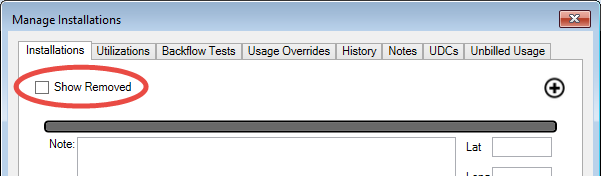
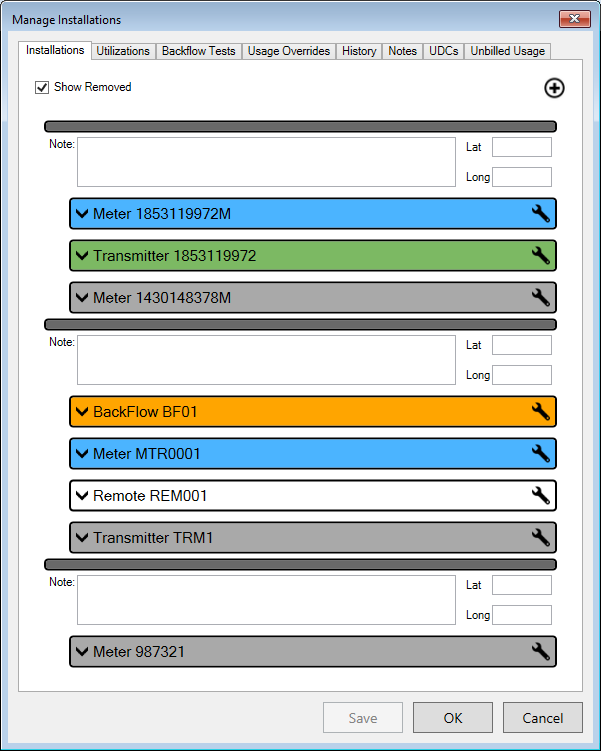
By default, only the devices that are currently installed are listed. However, the removed items can be included in the list by checking the Show Removed box that appears at the top of the device list.
Figure 245: Manage Installations - Show Removed Items
Once this box is checked, all historical devices and locations are added to the list:
Figure 246: Manage Installations – Removed Items Shown
Note that one removed item appeared in the first and second inventory locations on the list, and that a third inventory location also appeared which was not previously listed.
Note: Summary information for each device, whether current or removed, can always be viewed in the History tab.
The location note written in the header of the obsolete section is attached to the removed location and will be displayed (until edited or removed) every time the Show Removed box is checked. This is because inventory location notes are associated with the location regardless of the number/activity of devices attached.
Installed Items Listing
Within each device section, Inventory Location, there are several fields that can be edited. Some fields apply only to certain types of devices, so some will not be available for all devices.
Note. Enter any pertinent notes concerning the device. This can be useful for notes indicating where the device is attached, for instance.
Note: There are header notes and device notes. Transmitters are associated with meters and backflow devices, and each such association has a header note field in addition to the note field provided for each item.
Lat and Long. If relevant, specify the latitude and/or longitude where the device is installed. This can be useful for very large properties.
The headers for the items are color-coded. Blue corresponds to meters, backflow device headers are orange, transmitter headers are green, etc. Gray headers are for items that were once installed but have been removed.
Device Details
The details section for each individual inventory item can be collapsed or expanded for review. A few of the fields within these information sections can be manually edited from within this screen.
Date Installed. All inventory items have this field. This is the date when the device was associated with the Location, automatically entered by the system when the installation is documented. It can be edited as needed. Type in or select a date from the drop-down calendar.
Read Sequence. This field applies only to meters. This is the position of the device within the reading route. The displayed position is not manually editable. However, it can be changed by clicking the Browse button and moving the item up or down within the Resequence Route screen that opens. Refer to Meter Readings for more information on this function.
Maximum Estimates: This is the number of times the device can have an estimated reading.
Hazard Level. This item applies only to backflow devices. If applicable, select the Hazard Level code from the drop-down menu. If the item you need is not available, use the Add button next to the menu to create a new code.
Isolation Condition. This item applies only to backflow devices. If applicable, select the Isolation Condition code from the drop-down menu. If the item you need is not available, use the Add button next to the menu to create a new code.
Note. Each device has a note field. This note pertains only to the item at the particular location. Any text entered/edited will remain until the item is removed from the Location in question.
If changes are necessary for details other than the above, they need to be made using the Edit tool provided or from elsewhere within UMS. Editing embedded details is discussed below.
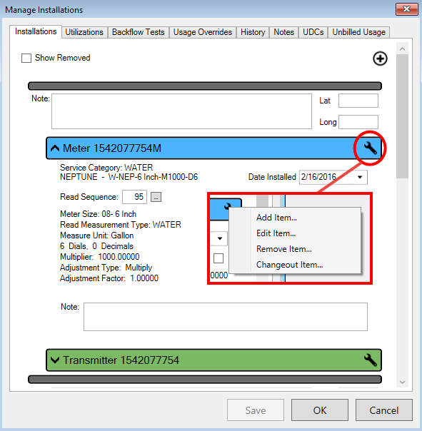
Installation Management Tools
Adding new inventory locations is an important function, already discussed above. Once an inventory location has been added, its devices will need to be managed using the configure tools associated with each item. These are located in the pop-up menu that opens when the Wrench icon (
) is clicked on individual inventory item headers.
Four tools are provided. Three of these (Edit, Remove, and Changeout Item) apply directly to the selected device, and therefore, care must be taken to click the wrench icon for the particular item in question. The Add Item option, however, applies to the selected inventory location, and the add function from any item will add an item to its particular inventory location.
Figure 247: Installations Tab - Item Management Tools
Add Item
As noted above, inventory items can be added either to a new inventory location (through the Add (
) feature at the bottom of the inventory list) or to an existing one using the wrench icon for an item already in the existing location. Either option will open the same Install window. The only difference will be where the new item is attached once it is created.
Figure 248: Manage Installations Add Item
Initially, this will be a generic screen, containing only date and serial number fields. The “Incoming” label indicates that you are adding (installing) a new item.
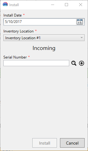
Install Date. This will be the date the new item is installed. This field defaults to the current date, but can be edited, as needed, by typing in the box or by selecting a date from the drop-down calendar.
Inventory Location. This will default to the Inventory Location from which the icon was selected. You can change the inventory location if it is not correct, as well as, add to a new inventory location.
Serial Number. If you know the full or partial serial number of the item to be installed, type it in the box and press Enter or click the Search icon. A search window will appear, where you can select the desired item. If necessary, you can further narrow your search from within this window. (Refer to Searching for details on using the Search window.)
Note: If the item you need is not found, it may already be in use. However, it may be a new item and you may need to create it in UMS. See Creating Inventory Items for details.
The types of items available as standard UMS installations are Remotes, Transmitters, Backflow Devices, and Meters. Other custom device types may be set up for your system as needed. Refer to Creating Inventory Items for details. The item types are listed alongside the identification information in the search results, for easy reference and type sorting.
Once the item Serial Number is filled in, the screen will change slightly, according to the type of item selected:
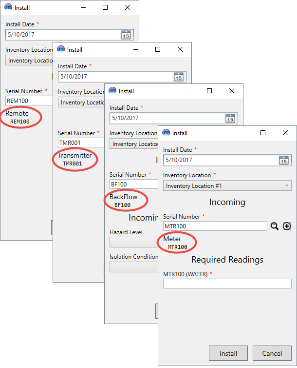
Figure 249: Install Items – Screen Variations
Each of these windows will indicate the selected inventory item type and serial number just beneath the selection box. If you have selected an incorrect item, you can re-select.
The available edit fields will be those required for the type of item selected, as defined when the inventory item types are created. The four standard UMS types will be discussed here.
Meter installations will have a field for the meter reading at the time of installation. Backflow devices will have Hazard Level and Isolation Condition drop-down boxes. Remotes and transmitters will have no additional required fields.
After you have entered all required information, click Install to add the inventory item to the Location installations list, either as a subunit in an inventory location grouping or as a new inventory location item.
Edit Item
The Edit option will open the Edit Inventory Item window. All previously-entered details for the item in question will be displayed, and some of these can be manually edited.
This window has several tabs. There are five tabs that are common to all device types. In addition, there are device-specific tabs, which will contain fields relevant to the specific device type chosen (backflow, meter, or transmitter). Which of these device tabs appears will depend on how the item was set up when created. (Refer to Creating Inventory Items for additional details.)
General
Figure 250: Manage Installations Edit Item – General
This tab provides general information about the device and its status. Some information can be directly edited. Information in this tab includes:
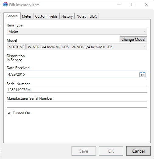
Item Type. This is the type assigned to the item when it was created. It can be one of the standard UMS types (backflow, meter, remote, or transmitter) or a custom type. This field cannot be changed from this screen.
Model. This is the model assigned to the item when it was created, generally a composite of the Manufacturer, Model Number, and Model Description entered during setup. It cannot be changed from this screen. Edits can be made through Setup > Setup Inventory Model. Refer to Creating Inventory Items for further information.
Change Model. This allows you to change the model associated with the device. Click the button to see the Edit Inventory Item Model screen.
Information regarding the current model will be listed on the left. A list of Compatible Models will display by clicking the drop down in the top right of the screen.
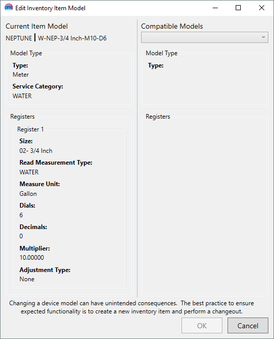
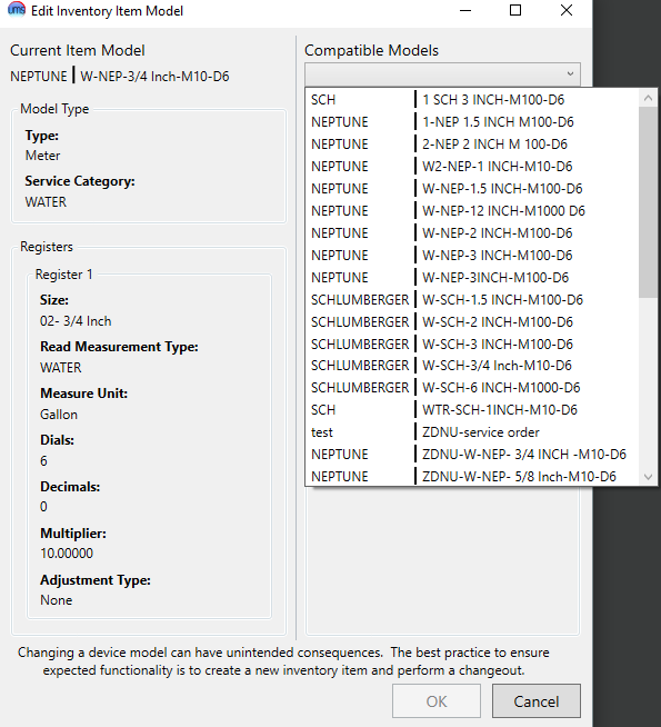
Figure 251: Edit Inventory Item Model Figure 252: Edit Inventory Item Model Compatible Models
Select the appropriate model from the list and the new model details will display on the right of the screen. Once the correct model is displayed click the OK button.
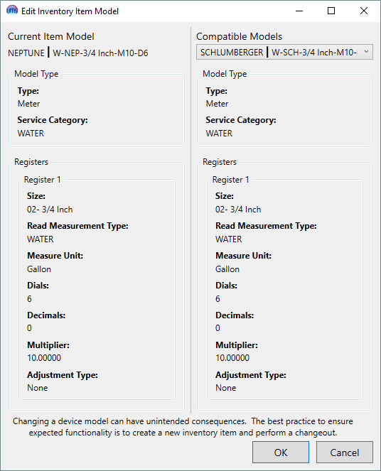
Figure 253: Edit Inventory Item Model – Complete
Disposition. This is a description of the status of the item. If it is associated with a Location, and thus available for editing in this screen, this description will be In Service.
Date Received. This is the date when the item was received by the company. This date is assigned when the item is created within UMS. It can be edited as needed, by either typing in the field or selecting a date from the drop-down calendar.
Serial Number. This is the serial number assigned to the item, either the manufacturer’s serial number on the device or another identifier created by your company. It is assigned to the item when it was created, but can be edited as needed.
Manufacturer Serial Number. This is another identifier field. It may be left blank, particularly if the manufacturer serial number was used as the Serial Number, above. This item can be edited as needed.
Manufacturer Model Number. This information was entered when the item was created, and is generally one of the composite parts of the Model described above. It cannot be edited from this screen, but edits can be made through Setup > Setup Inventory Model. Refer to Creating Inventory Items for further information.
Turned on. This box will usually be checked on for an item in service. It can be toggled off or on as needed. Meters that are turned off will have no usage, but billing minimums will continue to apply.
Note: This on/off tag can be useful in several ways, including using it as a limit option for reporting and for meter reading. Also, if usages are found for meters that are turned off, they will be flagged in the exception report, indicating that some sort of follow-up is needed.
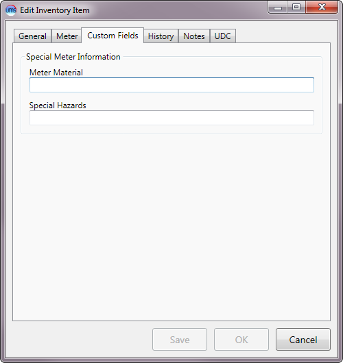
Custom Fields
Figure 254: Manage Installations Edit Item – Custom Fields
This tab contains any custom fields created for this type of item. These are set up in Setup > Setup Inventory Item Type > Inventory Item Custom Fields. (Refer to Creating Inventory Items for more information.)
The information included in any special fields set up of this type of item can be edited as needed from this window.
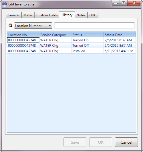
History
Figure 255: Manage Installations Edit Item – History
This tab summarizes all activity for the inventory item being edited. This list includes all actions performed for the meter, such as installation/removal or turning the meter off/on. Setting details such as item notes, custom field or code entries are not tracked in this history.
At the top of the tab is a search box, where you can limit the list by Location Number, Service Category, Status, or Status Date. Note that these search options are also the table fields, and the results table can be sorted (ascending or descending) by any of them by clicking on the table headers. Click once to sort ascending and again to sort descending.
The rest of the tab is read-only. The entire history of an item is listed, including installations at other UMS Locations:
Figure 256: Manage Installations Edit Item – History Details
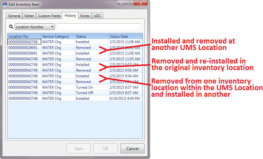
The meter history example above shows that the item was originally installed at the current UMS Location (42748), changed out briefly to another Location (28691), then and returned to Location 42748.
The meter in question was also moved from one inventory location grouping to another, then back again. Note that these installations/removals are recorded, but they are all associated with the same UMS Location (42748). For specific details of the associations of this meter with device groupings, exit the inventory history, and click the Show Removed box to show where this particular item has been installed. All old installations will be displayed with gray headers.
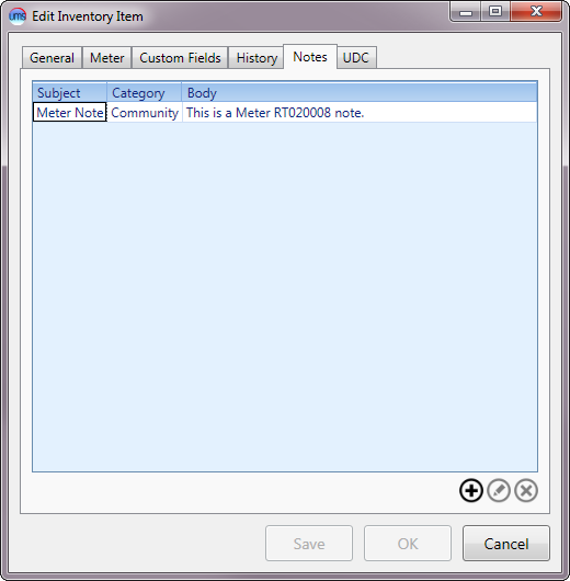
Notes
Each item will have a tab for item notes. These notes should not be confused with the inventory location notes or the item/location notes from the Installations tab.
The Notes tab in the Edit Inventory Item window is for notes that will be attached to the specific selected item only. These notes will follow the item, regardless of installation status/location, until edited or removed.
Note: Any items created within this tab will also appear in the Manage Installations > Item Notes Tab, labeled with the item number in question.
Figure 257: Manage Installations Edit Item - Notes
Use the Add, Edit, and Delete buttons beneath the notes list box to manage these item notes.
To delete a note, select it in the table and click the Delete button. The note will be deleted immediately. You will not receive confirmation, but the item will disappear from the list.
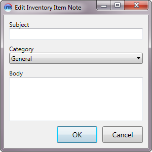
To add or edit an item, either click the Add button or select an item and click Edit. This will open the Edit Inventory Item Notes dialog box.
Figure 258: Edit Inventory Item Notes
Type a subject for the note in the Subject box and the text of the note in the Body field. The note Category is set to General by default, so selecting another category from the drop-down menu is optional. Click OK to save the note and return to the Notes tab.
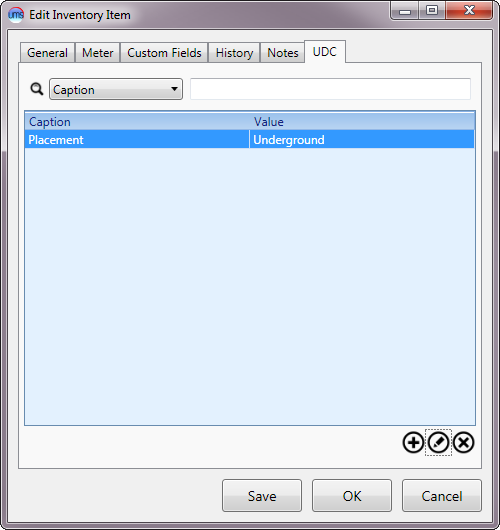
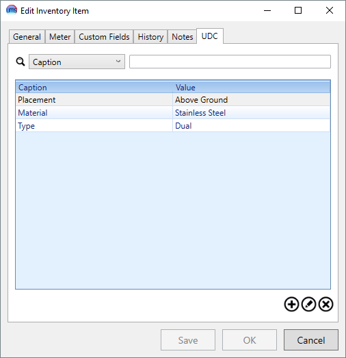
UDC (User-Defined Codes)
Figure 259: Manage Installations Edit Item – UDC
Any User-Defined Codes (UDCs) that have been attached to the item in question will appear in this window. Use the Add, Edit, and Delete icons beneath the code list box to manage the UDCs for the item.
To delete a code, select it in the table and click the Delete button. The note will be deleted immediately. You will not receive confirmation, but the item will disappear from the list.
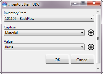
To add or edit a code, either click the Add button or select an item and click Edit. This will open the Inventory Item UDC dialog box.
Figure 260: Inventory Item UDC
Enter the required information:
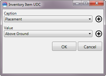
Caption. This box will only be active if you are adding a new item. You will not be able to change this selection when you edit and existing code item. Select a code from the drop-down menu.
Value. Select from the possible values associated with the code that are available in the drop-down menu.
If the caption or value that you need has not been created, you can define new ones through Setup > User Defined Code. The same Add/Edit functions can be accessed using the Add buttons next to the Caption and Value fields, so that you need not exit the window to create the necessary codes.
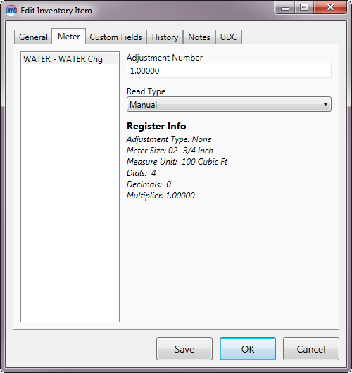
Meter
Figure 261: Manage Installations Edit Item – Meter
This tab contains information specific to a meter item, and is visible only when a Meter is being reviewed/edited.
On the left-hand side of the window is a box for selection of Service Category.
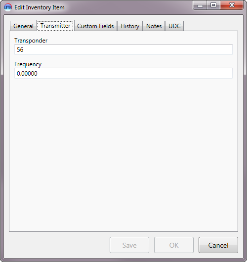
Transmitter
Figure 262: Manage Installations Edit Item – Transmitter
This tab contains information specific to a transmitter item, and is visible only when a Transmitter is being reviewed/edited. The Transmitter tab contains transponder and frequency information for the item. These fields are optional and do not affect UMS operation.
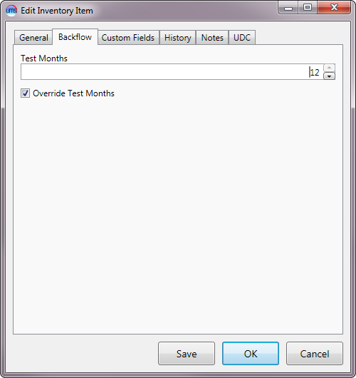
Backflow
Figure 263: Manage Installations Edit Item – Backflow
This tab contains information specific to a backflow device, and is visible only when a Backflow device is being reviewed/edited.
It contains test timing information for the one specific device in question. There is a default setting that is defined for the backflow device type, but the information in this particular tab applies to just the item being reviewed.
Test Months. Enter a number between 1 and 12, or use the arrows at the right side of the field to step the number up or down.
Override Test Months. It’s completely unclear to me what this button does.
Remove Item
Selecting Remove Item will open a Remove window. The window will be similar for all item types, but the text will vary. Also, meter removal will include readings that are not needed for other item removal.
Figure 264: Remove Item – Meter
Each of these windows will indicate the selected item type and serial number just beneath the removal date. This information is based on the item selected for removal, and cannot be edited.
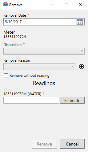
Removal Date. This is the date when the item is physically uninstalled. It defaults to the current date, but can be edited as needed. Type in the box or select a date from the drop-down calendar.
Disposition. Select the appropriate option (Available, Disposed, Repair, Return) from the drop-down menu.
Available means that the item is ready to be used again.
Disposed means that the item is to be discarded.
Repair means that the item is temporarily removed from service, pending repair.
Return means that the item is to be returned to the manufacturer or distributor.
Removal Reason. Select the reason for the item removal from the drop-down menu. All previously-saved reasons will be available in the list.
Note: If the reason you need is not present, add a new one by clicking the Add button next to the arrow, and creating a new description in the New Removal Reason window that opens.
Requested Readings. This section is only applicable to meter removals, and will not be present for other items. This section provides an area to enter readings for billing usage for the meter being removed, if necessary.
Remove without reading. This field is only applicable to meter removals, and will not be present for other items. If no usage should be billed from the meter being removed (e.g. meter incorrectly installed at location), check this box to skip entering a reading.
Remove all existing unbilled usage. This field is only applicable to meter removals, and when the Remove without reading box is selected. All unbilled usage for the device will be deleted when this item is checked.
[Meter ID]. This field is only applicable to meter removals, and will not be present for other items. The name of this field will be the ID for the meter being removed. Enter the reading at the time of removal in the box below.
Estimate. This field is only applicable to meter removals, and will not be present for other items. Use this button to estimate a reading instead of entering the read directly from the meter. Refer to Meter Readings for more details concerning this function
After you have entered all required information, click Remove to remove the item from the Location. This will return you to Manage Installations. If the Show Removed box is checked, the newly removed item serial number and information will now appear in the corresponding item details section with a gray header. If the box is unchecked, the newly removed item will no longer appear in the inventory item list.
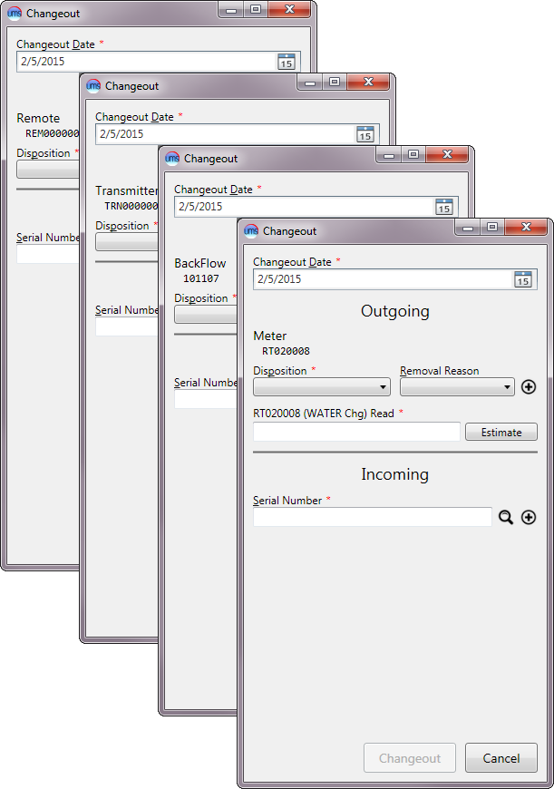
Changeout Item
Selecting Changeout Item from the tools menu will open the Changeout window and begin the inventory changeout process. As noted previously for adding, editing, and removing inventory items, the window will be slightly different, depending on what item (meter, transmitter, etc) is being changed out.
Figure 265: Changeout Items – Multiple Windows
Once the Changeout window has been opened for the specific item requiring change-out, fill in the applicable information from the outgoing and incoming items.
The example below is for meter changeouts. The window will be the same for non-meter items (transmitters, remotes, backflow devices, etc.), except that meter readings will not be necessary for non-meter inventory items.
Figure 266: Meter Changeout Process
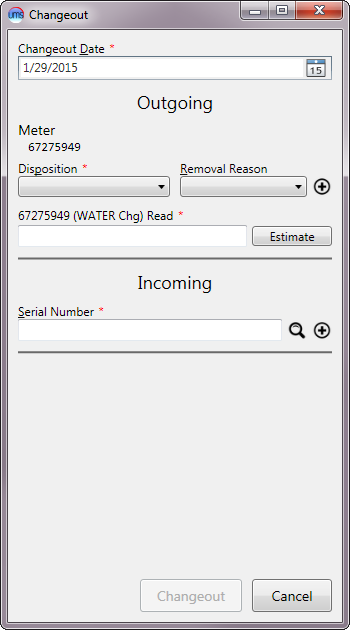
Changeout Date. Enter the date of the item changeout by typing in the field or by selecting the date from the drop-down calendar. This item defaults to the current date, but can be edited as needed.
Outgoing. This section is for recording the information from the item being removed. The ID of the item in question is displayed, for reference purposes.
Disposition. Select the appropriate option (Available, Disposed, Repair, Return) from the drop-down menu.
-Available: The item is ready to be used again.
-Disposed: The item is to be discarded.
-Repair: The item is to be temporarily removed from service, pending repair.
-Return: The item is to be returned to the manufacturer or distributor.
Removal Reason. Select the reason for the item changeout from the drop-down menu. All previously-saved reasons will be available in the list.
Note: If the reason you need is not present, add a new one by clicking the Add button next to the arrow, and creating a new description in the New Removal Reason window that opens.
[Meter] Read. This field is only applicable to meter changeouts and will not be present for other item changeouts.
The name of this field will include the ID for the meter being removed. Enter the reading at the time of removal.
Estimate. This field is only applicable to meter changeouts and will not be present for other item changeouts.
Use this button to estimate a reading instead of entering the read directly from the meter. Refer to Meter Readings for more details concerning this function.
Incoming. This section is for recording the information from the meter being installed.
Serial Number. Type the full or partial serial number for the new meter. Type Enter or click the Search icon to open the search window. Select (double-click) the correct meter from the search results. If necessary, you can refine the results by using the search tools provided. (Refer to Searching for more details on using the search function.)
Once a meter is selected, its serial number is displayed below the selection field, to show that it has been entered. A field for the new meter reading will also appear:
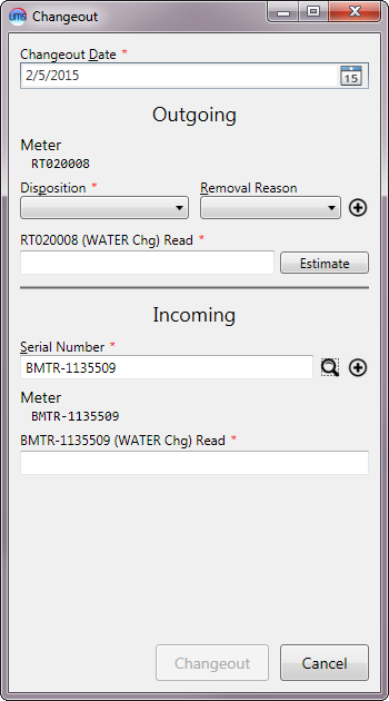
Figure 267: Meter Changeout Process with Incoming Item Selected
[Meter] Read. This field is only applicable to meter changeouts and will not be present for other item changeouts. Even when applicable, it appears only after a **Serial Number* has been selected.*
The name of this field will include the ID for the item being installed. Enter the reading at the time of installation.
Once the information is entered, click Changeout to complete the Inventory Changeout Process. This will return you to the Manage Installations. The new item serial number and information will now appear in the corresponding item details section, and the removed item will either not be shown (if the Show Removed box is not checked) or be shown under a gray header.
Utilizations Tab
Register Utilizations is a UMS function that ties service usage to location fixtures such as meters. This simplifies meter-based billing for complex situations, such as having separate rate structures for irrigation water and residential water consumption.
In UMS, meters are associated with Locations and not with specific services, and each meter can be associated with more than one register. Those registers generate readings, from which usage is calculated. A service can subscribe to that stream of usage so that the usage can influence the charge it generates. These subscriptions are called Register Utilizations.
Note: In order to manage Register Utilizations, applicable inventory items (meters, registers, etc.) must be installed and associated with the Location in UMS. Refer to Manage Installations – Installations section above for details for this task.
Locating Register Utilizations
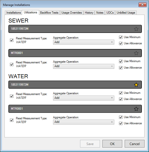
Register utilizations are managed for all metered services at a given Location from Manage Installations > Utilizations tab.
Figure 268: Manage Installations – Utilizations
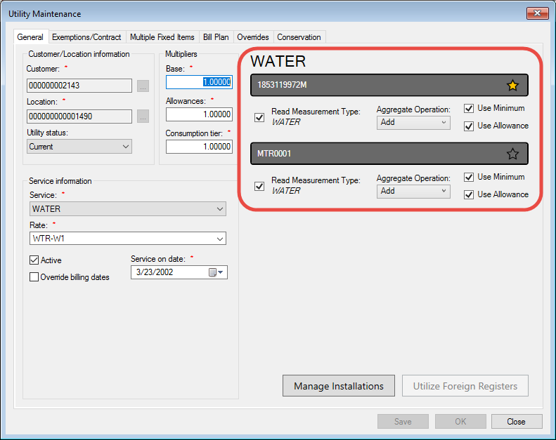
The very same information for a specific service can be found in the Utility Maintenance window General tab. (Refer to sections outlined in red.)
Figure 269: Utility Management - Utilizations
Note: The Manage Installations button in this Utility Management window will take you to the same Manage Installations screen as the corresponding buttons in the Account Control Panel Location tab and the Service Order Completion
Managing Register Utilizations
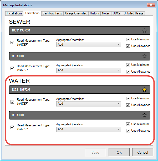
Every metered service at a given Location will have a meter utilization section in the Utilizations tab. Any meters that have been installed at the Location (refer to Installations tab discussion) will appear within each of these utilization sections.
Figure 270: Register Utilizations – Meter Selection Details
In the above example, two water meters have been installed at the Location. The type of meter is indicated in the installation details, and the applicability to each service is indicated by the checkboxes next to the meter measurement details.
Each utility has a separate listing of all meters, and each meter within the listings has a list of configurable details. The meter details are handled separately for each utility, the utility listed in the header for each section. Details for each meter include:
Activity Checkbox
When the checkbox to the left of the meter details is checked on, the meter applies to the service in question. When it is checked off, that meter (and any minimums or allowances that apply) will not be associated at all with that particular service, and the entire meter details section will be grayed out.
Read Measurement Type
This item is not a utilization detail. It is the measurement type associated with the rate code chosen for the given service. Refer to Rate Codes for additional details.
Aggregate Operation
This is the calculation method to be used to generate the usage for billing.
Add
The default operation for all meters is Add. This means that all usage from the meter will be added to all other specified usages (other active meters) for that utility to obtain the total consumption used for billing.
Total consumption for each billing cycle is the sum of the initial consumption for the cycle (which will be zero) and any usage amounts from active meters. If all meters have Add designations, then the total consumption will be the sum of all calculated usages.
Ignore
If Ignore is selected as the operator, the meter reading (and thus consumption level) for the meter in question will be ignored. This means that none of the usage from the meter will be included in the total consumption used for billing.
Note: Ignoring the usage in the consumption calculation does not exempt the Account from any minimum charge applied for that utility.
Subtract
The Subtract operation is applicable when multiple meters are used for more complex configurations within a Location. For instance, if a Location has a primary meter for all incoming water, and a sub-meter is installed to measure irrigation water, the total consumption of water needs to be divided between irrigation and household usage. Furthermore, sewer service would need to be tied to household usage only, not to irrigation water which does not enter the sewer system. This and other more complex setups can be handled by subtracting some usage levels from others.
Total consumption for each billing cycle is the sum of the initial consumption for the cycle (which will be zero) and any usage amounts from active meters. Any meters designated Subtract will add negative numbers to the sum. Subtracted usage for one service (in the above example, household water) may be added usage for another service (again in our example, irrigation water).
Select the operation (Add, Ignore, Subtract) that applies to a given meter for the specified utility.
Use Minimum
If this box is checked on, a fixed minimum charge will apply. This minimum is associated with the rate code selected for the service in question, and the fixed charge will automatically apply to the account, regardless of usage.
Note: If more than one meter is active for a given utility, the Use Minimum checkbox should only be checked on for those to which a minimum should apply. If multiple meters have this box checked, multiple minimums will be charged.
Use Allowance
If this box is checked on, a fixed allowance charge will apply. This allowance is associated with the rate code selected for the service in question, and the fixed charge will automatically apply to the account, regardless of usage below the allowance. If usage exceeds the specified allowance, the overage will be billed at the consumption rate.
Note: If more than one Use Allowance box is checked on for a given utility, the designated allowances for the associated rate codes are additive.
Primary Meter
Each meter details section has a star icon on the right side of the meter header. This star is used to designate the primary meter (or register) for each service. The primary meter is the one that is used to determine read and billing dates.
If only one meter is installed and the service is itself primary, the single meter will be default be the primary one, and the star will be yellow (
).
If more than one meter is installed, a primary one (if applicable) will be designated (
). These are active stars, and selecting a non-primary (gray) one will make its meter primary. The new selection will turn yellow, and the star for the formerly primary meter will toggle to gray.
If the service in question relies on another service for usage (for instance, sewer usage attached to water consumption), none of the meters for that service will be primary. The stars for meters applied to such services will be inactive, light gray (
) and unselectable.
Note: The color difference between a non-primary star icon and an inactive star icon may not be apparent on the dark background. However, they will be distinguishable by the fact that the associated service(s) will not have a primary meter selected.
Multiple-Register Meters
In some cases, a single meter may have more than one register. For example, a factory may have a high-flow water register for daytime shift use, and a low-flow water register for night shifts or other low usage times. Both registers may or may not physically be a part of the same meter, but they are treated as separate meters for consumption calculations.
For cases such as this, both meters (registers) will be installed at the location in question. These will be treated as separate meters within the Register Utilizations function. The same meter details (activity, aggregate operation, primary installation, etc.) will apply.
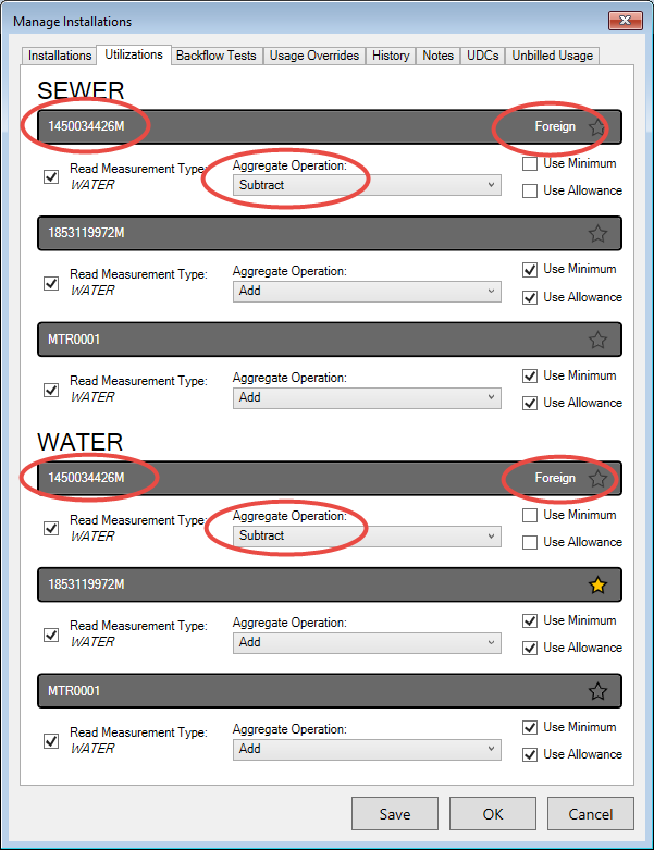
Foreign Register Utilizations
Foreign register utilizations are similar to the above example, in which the differences between two meters may be used to calculate usage. However, the foreign utilization feature allows the usage to be spread over multiple Accounts. For example, a second house might be built on an existing Location with a single supply line, and the second residence needs to be a separate Account with separate billing. Another example might be a trailer park with a single supply line and primary meter, with sub-meters assigned to the trailer stalls within the Location.
Foreign registers are applied specifically to a selected service, not to the Location as a whole. Therefore, foreign registers cannot be set up directly through the Manage Installations function. They must be created within the specific service (for example, Water) through the Utility Management page. Once set up, however, they can be managed just as other meters, through Manage Installations.
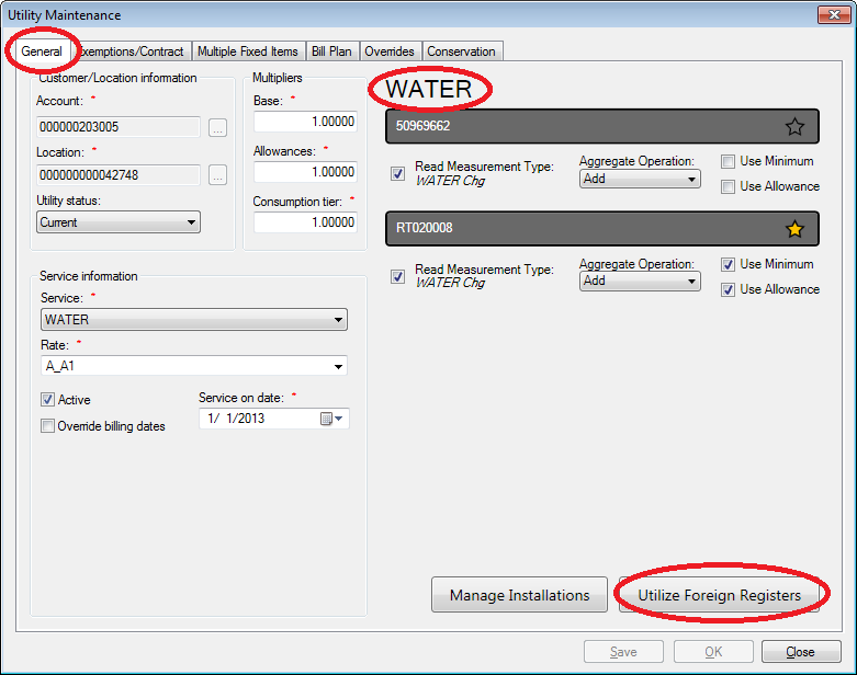
From Account Control Panel > Location, select the applicable service in the service details section and double-click to open the Utility Maintenance window. At the bottom of the General tab is a button called Utilize Foreign Registers.
Figure 271: Utility Maintenance – Utilize Foreign Registers
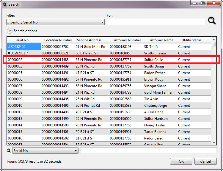
Click Utilize Foreign Registers to open a meter search window, where you can locate and select the foreign meter to be used.
Note: If you do not know the meter ID, you can search by Location or Customer or any other standard search field instead.
Figure 272: Utility Maintenance – Search for Foreign Registers
Once the desired meter (or Customer/Location) is located, double-click the search entry, or select and click OK. This will return you to the Utility Maintenance window, which will now include the new register.
Note: You may need to exit and re-enter the window in order to properly view the newly-created foreign register(s).
The foreign register is designated in the header as such. Handling of meter options for this item will be just like that of the Location meters, except that it cannot be made primary and it is for the designated service only.
Figure 273: Utility Maintenance – Foreign Register Applied
The hosted meter still exists at its original Location, and the meter details needs to be managed separately for the two Locations from this point on, because the details pertain to the two separate billing processes of the two Locations. Now that the foreign register has been added, it can be managed (as other meters) from either Utility Maintenance or Manage Installations. This applies to both host and hosted Accounts.
Foreign Registers in Utility Maintenance
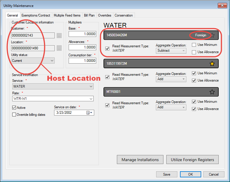
For correct billing at the primary (host) Location, the usage for the foreign Location must be subtracted from the total host Location usage. This is because the foreign Account is the one actually using the service, even though the host Location has the primary meter. Therefore, the Aggregate Operation field should be set to Subtract in the host location.
Figure 274: Utility Maintenance – Foreign Register Management
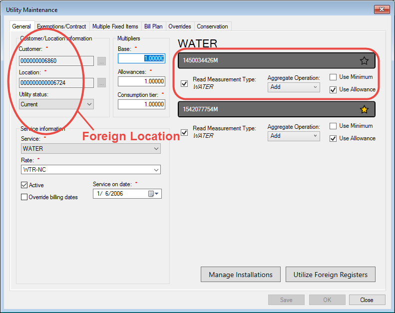
Within the foreign location, on the other hand, the register attached to the host Location can be primary at its home Location, and its Aggregate operation will need to be Add so that the usage not billed by the host meter will be properly billed to the foreign Account actually using the service.
Figure 275: Utility Maintenance – Foreign Register in Home Location
Foreign Registers in Manage Installations
Once the foreign register has been installed through Utility Management, it will appear in the Manage Installations Utilizations tab, just like other installed meters.
Figure 276: Manage Installations – Foreign Register Utilization
Note that although this foreign meter is now installed at the host Location, just as the others, it does not appear as part of the meter lists for other services in the list. This is because the installation of foreign registers is service-dependent and must be performed separately for each utility, if required.
Usage Overrides Tab
The usage override function allows you to override the consumption recorded for a specific meter or register. A Customer charge can be adjusted for a lower usage amount, while still properly tracking actual usage.
This can be useful in cases where, for instance, a large water leak has occurred. The Customer may not be charged for the entire amount, but the actual water that has passed through the meter still needs to be accounted for.
Overrides created through this function are for a specific register installed at the specific location under review. If the meter is removed from the location and installed somewhere else, the register level overrides will not come with it. Furthermore, if a meter with associated overrides is replaced with a new meter, the new meter will not inherit the usage overrides from the old meter.
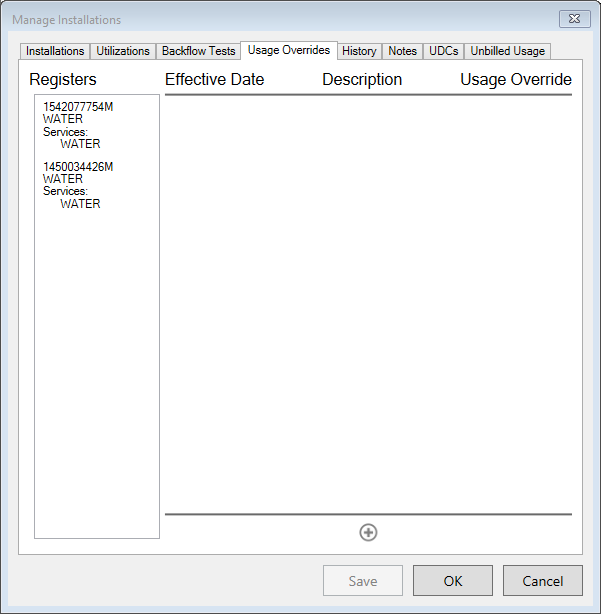
Figure 277: Manage Installations – Usage Overrides
In the above example, the Location in question has three meters installed for water. (Refer to Utilizations tab for more information.) These are listed in the box on the left.
Note: Foreign meters are not available for register overrides. Usage overrides must be created in the Location where the meter is installed.
In order to create an override, select the applicable meter from the list on the left. Any overrides that have already been created for this meter will show in the box on the right:
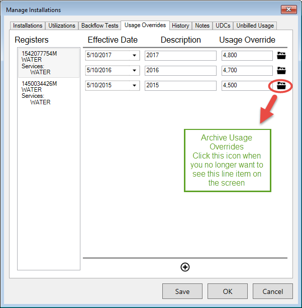
Figure 278: Usage Overrides Example
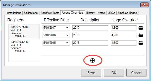
Adding Overrides
To add a new override, click the Add button at the bottom of the screen. A new line will appear at the top of the overrides list:
Figure 279: New Usage Override
When the new override line appears, fill in the following information:
Registers. This is a list of the installed meters, showing Serial Number and Services. If there is more than one meter, select the one to which the override will apply.
Effective Date. This is the date when the adjustment will be applied to bill calculation. The field defaults to the current date, but it can be edited as needed. Type in or select a date from the drop-down calendar.
Description. Enter a short description or reference to identify the reason for the override.
Note that the entry can be larger than the field, if needed, but a long description will cause the screen to scroll so that it is not easily read.
Usage Override. Enter the usage override that will be used for bill calculation.
Archive Usage Override. Click the icon at the end of the line when you no longer need to see the line item on this screen
Editing Overrides
Any of the override fields can be edited if needed, up to the point when it is archived. Click in the Effective Date, Description, or Usage Override fields and enter the new information as required.
Archiving Overrides
Once an override is created, it cannot be deleted. Click the Archive button (
) at the end of the override line to be archived. The line will remain in the list, but it will be grayed out and no longer editable.
History Tab
This tab shows the history of inventory items installed at the selected location. The History function in Manage Installations is similar to the installations history, except that the history provided is for all devices at the Location under review instead of all history (regardless of Location) for a particular item. Like installations history, items are categorized by Service Category, Status, and Status Date. However, Manage Installations > History lists all inventory items that were ever installed at the UMS Location in question, identified by serial number.
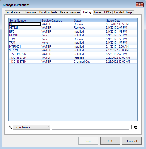
Figure 280: Manage Installations – History
The listed fields are Serial Number, Service Category, Status, and Status Date. These fields are also searchable using the search box below the table. The table can be sorted (ascending or descending) by any of the headers. Click once on any header to sort ascending, and again to sort descending.
Note: All item-related actions at the currently-selected Location are listed, but actions taken while a given item may have been installed at other Locations are not included.
A Print Preview icon is provided in the lower right corner of the window. When it is clicked, a Device History report is generated. From there, it can be printed or exported for use in another program such as Word.
Note: The report is created in order as the list appears when the preview button is clicked. The date column does not include the time stamp and is listed in front of the Serial number, but the information is otherwise the same as listed in the window.
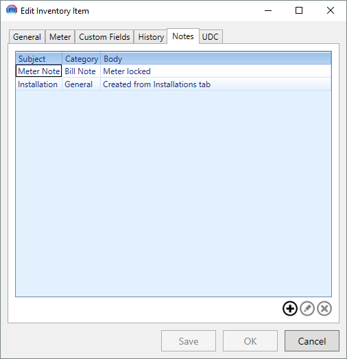
Notes Tab
The Notes tab contains a list of all notes for all individual inventory devices attached to the Location.
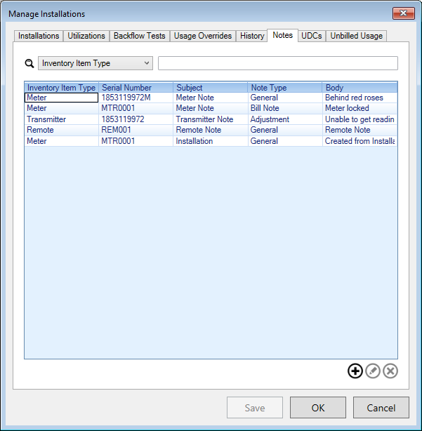
Figure 281: Manage Installations – Item Notes
Locating Item Notes
This lists includes all notes created in the Installations > Edit Item > Notes tabs for each individual item, gathered into this one location. The highlighted item in the above example was created from the MTR0001 meter item in the Installations tab.
Likewise, any notes created through this Item Notes tab are also present in the individual Installations > Edit Item > Notes tabs for the item designated in the note creation.
Example: The Meter MTR0001 note from the Notes tab displayed above (one created from each tab) are both present in Installations > Edit Item > Notes for Meter MTR0001:
Figure 282: Manage Installations Edit Item– Item MTR0001 Notes
Thus, notes can be both created and reviewed from two different places within Manage Installations.
Managing Device Notes
Use the Add, Edit, and Delete buttons to manage notes in the Notes tab.
To delete, select a note from the list and click Delete. The note will be deleted immediately. You will not receive a confirmation, but the item will disappear from the list.
Note: It will also disappear at the same time from the individual item Installations > Edit Item > Notes list.
To add or edit, either click the Add button or select an item and click Edit. This will open the Inventory Item Note dialog box.
Figure 283: Inventory Item Note
Note: If this is a new (Add) note, there will be error markers on the empty fields because nothing has yet been entered. These will disappear as you fill in the blanks.
Four fields are required:
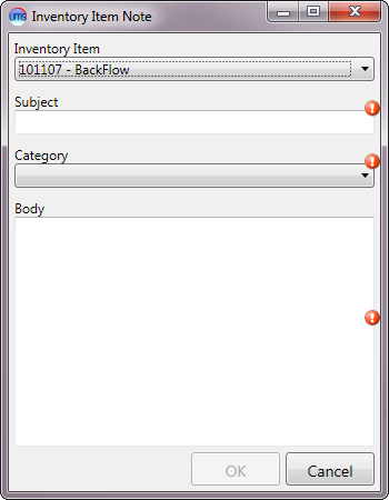
Inventory Item. This applies only to adding new notes. You will not be able to edit this for existing notes. Select the item to which the note will apply. This is a drop-down menu field, which will be populated automatically with all devices installed (see Installations tab) at the Location.
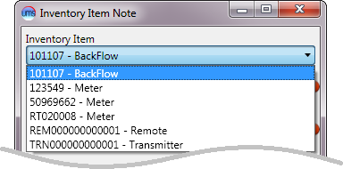
Figure 284: Inventory Item Note – Item Options
Note that both the serial number and the Item type are listed for easy reference.
Subject. Type a descriptive subject for the note.
Category. Select a category for the note from the drop-down menu. The categories include all the Note Types created in Setup, plus the standard limit options (Company, Community, Cycle and Route)
Body. Type the note text.
Note: There is no strict limit to the length of the note, but keep in mind that only the portion of the note that fits in the designated line in the Item Notes tab will be visible. The columns and the tab itself can be re-sized, but there will still be a practical limit to the note visibility.
UDCs Tab
The UDCs tab contains a list of UDCs for all individual inventory items attached to the Location.
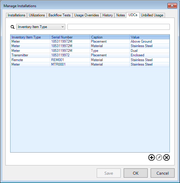
Figure 285: Manage Installations – UDCs
Locating Device UDCs
This lists includes all notes created in the Installations > Edit Item > UDCs tabs for each individual item, gathered into this one location. Likewise, any notes created through this Notes tab are also present in the individual Installations > Edit Item > UDCs tabs for the item designated in the note creation.
Example: The two Meter 1853119972M items from the UDCs tab displayed above are also present in Installations > Edit Item > UDCs for Meter 1853119972M:
Figure 286: Manage Installations Edit Item– Item 1853119972M UDCs
Thus, item UDCs can be both created and reviewed from two different places within Manage Installations.
Managing Device UDCs
Use the Add, Edit, and Delete buttons to manage notes in the UDCs tab.
To delete, select a UDC from the list and click Delete. The item will be deleted immediately. You will not receive a confirmation, but the item will disappear from the list.
Note: It will also disappear at the same time from the individual item Installations > Edit Item > UDCs list.
To add or edit a code, either click the Add button or select an item and click Edit. This will open the Inventory Item UDC dialog box.
Figure 287: Inventory Item UDC
Enter the required information:
Inventory Item. This applies only to adding new UDCs. This field will not be present for editing existing UDCs. Select the item to which the UDC will apply. This is a drop-down menu field, which will be populated automatically with all devices installed (see Installations tab) at the Location.
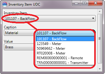
Figure 288: Inventory Item UDC – Item Options
Note that both the serial number and the Item type are listed for easy reference.
Caption. This box will only be active if you are adding a new item. You will not be able to change this selection when you edit and existing code item. Select a code from the drop-down menu.
Note: If you have already selected a code with a particular caption (“Material” in the above example) for a given item, you will not be able to select that caption again. The option will only be available for items which have not had that caption selected.
Value. Select from the possible values associated with the code that are available in the drop-down menu.
If the caption or value that you need has not been created, you can define new ones through Setup > User Defined Code. The same Add/Edit functions can be accessed using the Add buttons next to the Caption and Value fields, so that you need not exit the window to create the necessary codes.
Unbilled Usage Tab
The Unbilled Usage tab displays unbilled usage for all meters associated with the location. This includes active and removed meters. Click on the meter on the left side to view its unbilled Usage, Reading, Read Date, and Billed for Services. The Reading and Read Date fields can be changed on this screen. If changes are made, click Save or OK when they are complete.
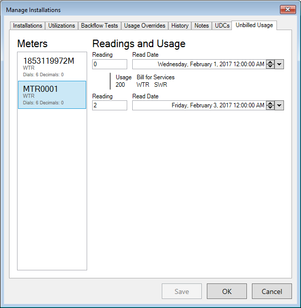
Figure 289: Manage Installations – Unbilled Usage tab